Sunday, January 21, 2024

Hyundai Level 2 EV Charging Efficiency about 88%


Unlike PV inverters, EV on-board chargers usually don't have efficiency specifications published by manufacturers.  Studies done on charger efficiency are limited in the number of vehicles that can be tested.  I decided to test the charging efficiency of a Canadian 2023 model Kia Sportage PHEV.

I performed the test with the Kyungshin EVSE that was provided with the vehicle, set to 12 amps.  The EVSE was plugged into a 240V outlet via a 18m, 10 AWG extension cord.  The L14-30R outlet is wired to the electrical panel with 6/3 aluminum cable.  Measurements were made at the electrical panel using a Peacefair PZEM-016, logged with a python program I wrote.  I initially took measurements with a clamp-style meter, but the readings were too variable, and could not account for power factor.

Considering the connectors and wire resistance, I estimate the losses between the electrical panel and the EVSE to be about 1%.  For a typical home level 2 30-amp charger installation, the losses would be much higher, likely over 2%.

The Sportage PHEV battery capacity is 13.8 kWh.  To charge from 20% to 100%, the PZEM-016 recorded 12.55 kWh of energy.  The energy stored in the battery was 80% of 13.8, or 11.04 kWh.  The efficiency is therefore 11.04/12.55 = 0.8797, or about 88%.

Sunday, November 26, 2023

Level 2 EV Charging Deep Dive


Electric vehicles have an on-board charger, which converts an AC input voltage to DC to charge the batteries.  These chargers are designed to accept 120 volt input for level 1 charging, and 208/240 volt input for level 2 charging.  The specs for the Hyundai OBC shown above indicate it can accept a wide range of 70 to 285 Vac, allowing it to work with almost any power grid in the world.  Note that it is the OBC, not the EVSE, that rectifies and boosts the voltage to charge the battery.  That's why an EVSE with a 120V 5-15R plug can be connected to a 240V source.

Although the Hyundai OBC is rated for 7.2 kW of output power, getting much more than 6 kW of input power has been difficult.  The first reason is that power to commercial buildings is usually 3-phase 120/208V, so charging stations usually provide 208V.  At the maximum input of 32 amps, that's 6656 watts.  Having used both ChargePoint and Flo charging stations, I've noticed the majority of them are limited to 30 amps for level 2 charging.  Those stations rated for 30 amps use 10 AWG flexible cord, which is limited to 30 amps according to table 12 of the Canadian Electrical Code.  30 amps at 208 volts is 6240 watts.  Charging at more than 30 amps requires a more expensive larger cable.

I've also found the OBC doesn't seem to pull the full amperage advertized by the EVSE.  The signalling used for J1772 charging doesn't communicate a precise amperage available to the OBC.  It transmits a sequence of pulses, and the duty cycle timing of the pulses indicates the available amperage.  I think the OBC reduces the current by a safety margin to allow for imprecise timing of the control signal pulses.  When connected to a Kyungshin IC-CPD set to 12 amps, the on-board charger draws about 11 amps.

Lastly, some charging stations don't always provide the power that they advertize.  Several of the ChargePoint chargers I've encountered are Leviton 4000 units.  They support 16 amps per head, or charging from a single head at 30 amps.  These stations are usually listed on the ChargePoint network as 6.6 kW, but with a 208V supply, you'll never see more than 6.2 kW.  When both heads are being used, your vehicle will charge at no more than 3.3 kW.

I think home charging makes a lot of sense, but I see limited value in public level 2 chargers.  I am not aware of any public chargers in Nova Scotia that accept payment by credit card.  They require users to first set up an account and install an app in order to active chargers.  When you do get a charger working, at a charging rate of 6 kW, you can't get much of a charge while you shop at a store or eat at a restaurant.  I've seen a few businesses that offer free charging for customers, but after the novelty factor of free charging wears off, I wonder how much use they will get.  Since charging at home costs 18.5 c/kWh including GST, getting free charging while you shop for a half hour only saves you 50c.

Wednesday, November 8, 2023

240V EV Charging for $5


We recently purchased a PHEV which came with a portable home charger/EVSE.  It plugs into a NEMA 5-15R outlet, and supports a maximum charging rate of 12 amps.  At 120 volts, the maximum charge rate is 1440 watts, and the charge rate reported by the vehicle is usually 1.3 kW.  The vehicle supports level 2 charging at up to 7.2 kW, but I didn't want to spend $400 to $500 for a good quality 30 amp level 2 EVSE.

The label on the portable EVSE listed an input of 12 amps and 120 volts, however I suspected 240 volts would be fine.  The EVSE just passes through the AC power, generating a PWM signal on a control wire to indicate the amount of current the vehicle's on-board charger can draw.  Of course, it's possible some home EVSEs for the North American market are built as cheaply as possible, and may not handle 240V.  I am confident our Kyungshin IC-CPD is built to accept 240V.  On the vehicle side, I checked the on-board charger label and saw that it has a wide input voltage, with a rating of 70-285Vac.  I have a 14-30R 240 volt outlet in my garage, which is the same type of outlet an electric dryer uses, giving me an available source for 240V power.

To make an adapter for the portable EVSE, I used the cord I cut off a broken dryer, and a 5-15R connector.  I used an Eaton 4887, which costs about $5 at local electrical suppliers.  The Leviton 515CV is another option.  The specs for the 4887 lists an input wire size of 12 to 18 AWG, however the 10 AWG stranded copper wires on the dryer cord were just able to fit.

With my portable EVSE adapter hack, the vehicle now charges twice as fast.  It's probably more efficient too.  The output of the on-board charger is 240-430 Vdc, and boost converter efficiency increases with a smaller difference between the input and output voltages.

Friday, October 13, 2023

Calculating Copper Wire Characteristics

For the early of my life I've relied on tables or similar references to look up things like copper ampacities and resistance.  Now I just remember a few constants, and can calculate what I need to know.

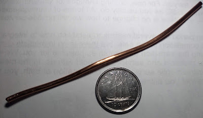
The photo above is a 12 AWG copper wire, commonly used in building wiring in the US and Canada.  It has a diameter of .0808 inches or 2.052 mm.  When used for building wire, it is typically limited to carrying 20 amps of current by breakers or fuses.  For circuits carrying more current, 10 AWG wire with a diameter of 2.587 mm can be used.  For a change of 2 AWG in wire size, the change in diameter is always 1.26, and therefore the change in cross-sectional area is 1.26^2.

The cube of 1.26 is 2.0, so an increase in size of 3 AWG will double the cross-sectional area of the wire, and reduce the linear resistance by half.  The resistance of 10 AWG wire is 1 ohm per thousand feet (304.8 m), so the resistance of 16 AWG wire, often used in extension cords, is 4 ohms per thousand feet at room temperature.  The amount of heat generated in a wire is calculated with the formula P=I^2xR.  If 10 amps is flowing through 1000 feet of 16 AWG wire, the power dissipated will be 10^2 x 4 or 400 watts.  If the wire is 10 AWG, and the current is 20 amps, the power dissipated will be the same 400 watts.  However voltage drop will be lower, since V = I x R.  The resistance of 10 AWG wire is a quarter of 16 AWG, so the voltage drop in the 10 AWG wire with 20 amps will be half of the voltage drop of the 16 AWG wire with 10 amps.

The resistance of copper increases with temperature, by 0.393% per degree C, so increasing the temperature by 25 C will increase the resistance by almost 10%.  Calculating temperature increase due to power dissipation is quite complicated, so it is common in electrical codes to consider an ambient temperature of 30 C, and a temperature rise in the wire of no more than 30 C.  Because of that, most wire sold in Canada that is CSA certified will use insulation rated for at least 60 C.  The most common category of wire used in residential construction, NMD90, has an insulation temperature rating of 90 C.

On a final note, a wire labeled 16 AWG might not really be 16 AWG.  I generally trust the electrical distributors like Rexel and Wesco, however before using some battery wire from a discount hardware store I'd inspect it carefully first.

Saturday, May 13, 2023

MODBUS communication with Solis 4G-US inverters

Solis single-phase inverters have a circular RS485 connector supporting MODBUS communication.  The connectors can be difficult to find for sale outside China, so using a wifi data logger stick is a more straightforward way of communicating with the inverters.  IGEN Tech is the OEM for the Solis wifi data loggers, which IGEN also sells under the SOLARMAN brand.  While the same circular connector is used by many other inverter manufacturers such as Solax, RENAC, and KSTAR, the logger firmware is customized to read and report the MODBUS registers for a particular manufacturer.

The LSW-3 series of wifi loggers allow external programs to perform MODBUS queries via a TCP connection port 8899.  I believe this is a variant of the MODBUS/TCP protocol that is assigned TCP port 502.

To perform MODBUS queries, I used pysolarmanv5.  To connect to the logger pysolarmanv5 requires the logger serial number and IP address.  Initially I read the serial number off the label of the logger, and looked up the IP address from the admin page of my router.  Later I noticed solarman_scan.py, which sends a broadcast UDP packet which the data logger replies to.  I sometimes had to run it more than once before the logger responded to the scan packet.

The Solis 4G-US series inverters are Sunspec MODBUS certified, and have the well-known 32-bit ‘SunS’ identifier (0x53756e53) at address 40001.  This means it should be possible to read the registers by decoding the SunSpec information models and inverter device IDs.  SunSpec shares some example code, however I haven't been able to figure it all out.

I couldn't figure out the Solis registers using SunSpec, but I was able to find the register documentation from Ginlong.  The AC output power and DC input power are 32-bit registers at address 3005 using MODBUS function code 4 (input registers).  I wrote a python program to read the output and input power and calculate the efficiency.  It also reads the inverter temperature, and outputs the data every 5 minutes.  I also wrote a small AWK program to calculate the weighted average of multiple samples.  The code can be found in my github repo.

Over multiple days of output in the spring of 2023 including sunny and cloudy days, I observed an overall efficiency of 94% for a Solis 1P4K-4G-US.  For a Solis 1P6K-4G-US I observed an average efficiency of 95%.  This compares to respective advertised CEC weighted efficiencies of 97.5% and 97.0%.

Monday, April 10, 2023

KSTAR Single Phase String Inverters


KSTAR New Energy makes single phase grid-tied inverters ranging from 1 kW to 10 kW.  I tested a 3000S, a 5000D, and a 6000D that were produced in KSTAR's factory outside of Shenzhen.  Their single phase inverters are marketed for locations with a 230 V line to neutral (L-N) grid.  They also work with the split phase 240 V line to line grid that is typical in the US and Canada.  They do not have UL 1741 certification, so they would require special engineering approval to be used for permanent installations with most US and Canada power utilities.

Residential inverters used in the US and Canada usually have an attached junction box with terminal connections for DC and AC wiring.  In the rest of the world, inverters usually have MC4 connectors for the DC string input, and a watertight three-pin plug connection for the AC output.  It is much more convenient having the plug connections when testing inverters and PV panels.  It also avoids potential electrical code concerns when DC wiring up to 600 V and 240 Vac are in the same junction box.


The KSTAR inverters all included MC4 crimp connectors for terminating the DC strings.  The AC connector will accept SOOW or SJOW cable with a outside diameter of up to 16 mm.  I used 3-wire 12 AWG SOOW cable that is rated for up to 25 Amps.

The 3000S has a single string input, and a "nominal" output power of 3 kW.  It is a light inverter, with a stated weight of 8 kg.  Out of the box, the measured weight was 7.3 kg.  The light weight makes it very easy for a single person to install.  When hooked up to a test string of 10 72-cell panels, the efficiency was 85-86%. This is much lower than the spec efficiency of 97% or the 96% efficiency at nominal 380 V listed on the inspection and test sheet that was included with the inverter.  With input power of 3070 W and input voltage of 367.7 V, the output power was 2620 W, for an efficiency of 85.3%.  KSTAR sales and engineering were unable to explain the low efficiency.


The 5000D and 6000D have the same external dimensions and connections on the bottom.  The weight of the 5000D is 11.74 kg, while the 6000D weighs 12.48 kg.   This suggests the 6000D has different internal circuitry, likely larger inductors and capacitors, to support the higher power rating.

The efficiency of the 5000D and 6000D inverters ranged between 89 and 91%.  The screenshot of monitor data below shows a total input power of 6240 W with AC output power of 5570 W, for an efficiency of 89.3%.  This test was done with a large difference between the PV1 and PV2 voltages to represent typical residential PV installations which are not optimized for the inverter's 380 nominal string voltage.


The KStar inverters are reasonably priced and easy to install, but the low efficiency makes them unattractive compared to Growatt and Ginlong Solis inverters.

Wednesday, October 5, 2022

DC Wiring Losses in String and Microinverter Solar PV Arrays

There are two common ways of wiring solar PV arrays.  Each panel can be connected to a microinverter, with each microinverter connected in parallel to an AC bus.  Alternatively, panels can be connected in series, with one or more DC strings connected to an inverter.  Although there is debate over which design is best, at Solar Si, we prefer string inverters.  This is an analysis of DC wiring losses with an array of 8 72-cell LONGi PV modules of about 450 Watts each.

There are two sources of wiring resistance in the array.  The first is from the wire itself, and the second is from the connectors.  The 12 AWG wire used for the panel output cables has a resistance of 5.2 mOhm/m.  The MC4 connectors are specified to have a contact resistance of less than 0.5 mOhm.  While this may be the resistance when tested in a clean and dry factory, test results in warm and humid conditions show a much higher resistance.  Reliability Model Development for Photovoltaic Connector Lifetime Prediction Capabilities indicate resistance in the field is likely to be around 2.5 mOhm.

For the string array, the panels are arranged in the portrait configuration, with the inverter situated 1m from the array.  The panels are about 1.06 m wide, making the length of the array 8.5 m.  Each panel has a 20cm and a 40cm negative and positive output cable.  Unlike the 12 AWG wire used for the PV panel output cables, in Canada, field wiring for PV strings is almost always done with 10 AWG RPVU wire.  This has a resistance of 3.28 mOhm/m, and a total of 10.5 m are used for the array.

With 8 panels, there are 7 connections between panels, plus two connections at the ends mating with the RPVU wire.  The DC connections on the inverter are usually not MC4, but for simplicity the resistance is assumed to be the same.  Adding the positive and negative connections connections to the inverter, the total comes to 11.  Here's the calculations for the total resistance:

10.5 m * 3.28 mOhm/m = 34.4 mOhm
12 AWG 0.6 m panel cables * 8 = 4.8m, * 5.2 = 25 mOhm
11 contacts/string * 2.5 mOhm = 27.5 mOhm
total: 86.9 mOhm

For the microinverter array, the optional 1.4 m PV panel output cables will be needed in order for the cables to reach the corresponding microinverter.  This increased the total length of 12 AWG wire to 22.4 m.  Here's the calculations for the total resistance:

12 AWG 2.8 m panel cables * 8 = 22.4 m, * 5.2 = 116 mOhm
16 contacts * 2.5 mOhm = 40 mOhm
total: 156 mOhm

Although the microinverter configuration higher resistance losses, they are not significant.  During peak power output, DC current is about 10 Amps.  Using P = I^2 * R, power losses are around 0.5%.  Most of the time the array output current is much less than 10 Amps, so the average power loss is much lower.  There are additional losses from the AC bus connectors, which are also not significant.

In conclusion, power losses are higher with microinverters than string inverters, but they are not significant.  The justification for choosing string inverters lies more with the cost savings in material and labor.  For an array with 16 panels, the cost of a 6 kW inverter with 2 string inputs is less than half the cost of 16 Enphase IQ7A microinverters.